For those that have purchased AutoCAD Revit Building Series, the temptation is to continue to use AutoCAD for fabrication detailing, but CADlineÝs Paul Woddy has long given up on AutoCAD in favour of the intelligence and speed of Revit.
Early editions of Revit did not hold construction detailing as a major selling point (long-term Revit users may spot a slight understatement there!) and during the early adoption phase of the software I regularly fell back on a decade of AutoCAD experience when it came to the nitty-gritty of getting fabrication drawings finished within a time frame. This opinion is now somewhat out of date, but the principle of using AutoCAD alongside Revit is far from obsolete, especially with the almost universal practice of purchasing Revit in the form of Autodesk AutoCAD Revit Building Series – Revit and AutoCAD bundled together in the same box, providing each desktop with access to both applications under the same license.
One reason for Autodesk providing this bundle option at such a competitive price is to present an easy transition path to Revit for those that are perhaps reluctant to face the downtime associated with a software learning curve; something to fall back on whilst getting up to speed.
In practice, we tend to advise all of our customers buying Revit to opt for the series for a number of reasons. Firstly, it has to be a strong argument to suggest switching software platforms in the advanced stages of an ongoing project or in the reviewing, tweaking and updating of archived projects. Secondly, the deployment of Revit across a team usually means that its use is initially restricted to key individuals in the concept and design development process.
Working with DWGs
As the project enters Stages D and E with a potentially larger team of draughtsmen it can be deemed prudent to switch to AutoCAD in order to make use of the abundance of DWG-based knowledge on the market which, when considered along with the relatively low cost of AutoCAD LT means that a large team of detailers need not be trained in new technology in order to get the project detailed and finalised for a relatively low cost. The added factor of training a potentially transient workforce gives further credence to this argument.
Even if the detailing is being generated externally in AutoCAD or LT, the basis for the details originate with 3D Revit geometry and the completed details can be imported back into Revit to co-ordinate the finished drawing set. Bearing all of the above in mind, our implementation plan will more often than not include a gradual deployment of Revit starting in the conceptual design space and working out to publication. We tackle the fear factor head-on by demonstrating that an efficient jump to AutoCAD can be initiated at any stage without major issues or rework, the team therefore feel more comfortable pushing Revit further forward in the project. Over a very short period, user confidence in own ability grows and the switch to AutoCAD becomes less and less appealing or required.
That said, the use of legacy data, even on an elemental basis will continue for a long time. Almost all practices have access to a library, built over many years, of pre-defined details or common arrangements of element groups that form the basis of detailing. Furthermore manufacturers often produce DWG details of their catalogue of components for use in CAD. Either way, this information can still be used inside Revit, without having to rework or redraw the linework.
What this means is that I can use a very simplistic one-size-fits-all window for my 3D and GA views whilst in the section or callout, where I need to see more accurate information, I simply turn off the visibility of the Revit window and import the anatomically correct detail. On the finished result, you cannot distinguish between the Revit and the DWG linework. In the long-term, importing the DWG information directly into the simplistic window component means that every time you cut a section through an instance of that window, you will see the more detailed version. The result being a library of very simple geometry, with an abundance of useful tabular data for schedule purposes attached, along with an accurate detail view.
Detailing in Revit
Revit is now more than capable of fabrication detailing and I have long since given up on AutoCAD in favour of the intelligence and speed of Revit. At this point, let me explain the idea of detailing, the Revit way. Revit is used to generate a digital prototype of the building, assimilating the real-world scenario as closely as possible and the software is capable of taking this theory to the nth degree, which is not always efficient in terms of time and hardware power. The mantra that I teach in deploying Revit is a simple one:
ýModel as simply as you can get away with; Detail as much as you need.¯
In practice, this means that 3D modelling to a GA stage is practical and speedy, whilst beyond 1:100 or 1:50 we are in danger of getting bogged-down with unnecessary 3D modelling and hence losing all the advantages so far realised in using Revit. To this end, the detailing functions of Revit allow view-specific 2D cosmetic patches to be quickly and easily applied over the top of the 3D geometry.
The tools at handÍ
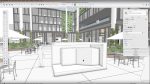
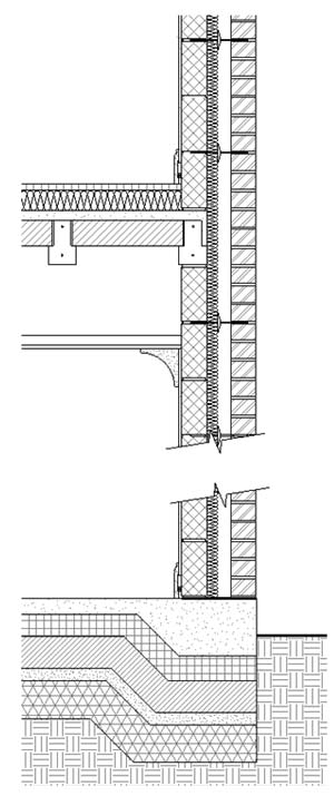
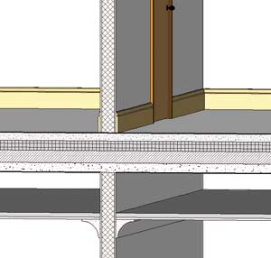
In the example in Figure 1, a section has been cut through the model to show a section of wall. The composition of the wall and floors is displayed to us simply as thicknesses of materials as shown in Figure 2. Rather than model the sweep of the skirting boards and other mouldings throughout a building, the profile is applied as a 2D detail in relevant views.
Coursing information and other recurring patterns are applied using a repeating detail tool, whereby the detail component of a Ùbrick with mortar jointÝ for instance is repeated at 75mm intervals along a sketched line, traced up the edge of the brick element in the wall composition. The same technique takes care of block-work, wall ties and the beam & block flooring.
The thickening of the slab shown at the base of this example is entirely a 2D alteration to the graphics of the 3D slab of constant thickness. Add to this automated keynoting, text, dimensions, filled regions (hatching) and good old-fashioned lines, arcs and circles and you have a pretty effective draughting tool and because we are not starting from a blank sheet approach, the time to produce the detailing is considerably reduced.
The downside to 2D modification is that we are potentially breaking the co-ordination link of the data and that our sections and call-outs no longer reflect the same data as the 3D model and schedules, hence the coverall nature of the above mantra in using the phrase ýsimply as you can get away with¯. In the case of the thickened floor slab for instance, the volume of concrete required will not increase to accommodate the extra material required. If you need to show it in 3D or in a schedule then perhaps you canÝt get away without modelling the item. Of course the counter argument to this is that schedules can derive more information through calculated fields than is initially obvious.
The bottom line is that there are no hard and fast rules, but rather there is a choice to make between accurate modelling and hence accurate scheduling or the quicker but usually more efficient method of employing 2D draughting where we can, combined with an acceptable inefficiency in the schedules. It usually comes down to a corporate guideline with exceptions for given scenarios. Let me change that slightly. There are no hard and fast rules bar one;
The method that gets the job you get paid for, done in the shortest time frame is the right one. If, along the way, the quality of your output improves, then thatÝs even better.