Tekla’s UK BIM Awards, an annual celebration of collaborative workflows and model based processes, honoured some impressive projects this year.
Winner Arup — National Museum of Qatar
The National Museum of Qatar, in Doha, is the flagship in an important series of cultural and educational projects being commissioned by the Qatari government. It is currently on site, having been in design since 2008.
Architect Ateliers Jean Nouvel drew inspiration from the desert rose, a crystalline formation found below-ground in saline regions of the desert. When imagined as a building, the result is a four storey, 300m by 200m sculpture of intersecting disc shapes up to 80m in diameter.
The structural solution settled on radially and orthogonally-framed steel trusses, supporting fibre-reinforced concrete cladding panels to create the required aesthetic and performance of the building envelope.
The key challenges for the design resulted from the highly complex geometry of the disc interaction. No two discs are the same; no two discs intersect each other in precisely the same way. The galleries and other key spaces in the building are created by the interstices between the discs; any alteration to the architecture involves moving discs and thereby moving the structure within the discs.

This has led to an evolution of systems and processes required to handle, manipulate and develop geometric ideas from the architect, and establish engineering solutions, before communicating them in their most useful form to the wider community.
Structural modelling
The structural team developed a parametric Generative Components script-based tool to automatically create wire-frame geometry in the correct position within the architectural Rhino envelope. The basic wire-frames were further populated with property and loading data using spreadsheet-based automation.
Key workflows
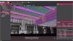
1.Architectural surface information was received in IGS format plus additional defining numerical data. Bentley Generative Components was used to process this data and produce a basic structural frame, which could be read directly by GSA structural analysis software. Rhinoscript tools were developed to read the geometric data from GSA into Rhino, and compare to the architectural IGS surfaces. This allowed fast manipulation of the framework to make structural connections and trim the structure to suit the architectural layout. The resulting GSA models were imported directly to Tekla using a Tekla plug-in tool, which could then be used to define the required Tekla objects. Once modelled accurately, including all required tapers, trimming and allowance for connection details, DWG and IFC files were exported to a common ‘live’ directory, which automatically imported into Navisworks for MEP and further architectural co-ordination.
2.1,600 piles, each individually designed with bespoke trim and toe levels, was carried out in Tekla using a macro script to read the required data from a suite of spreadsheets.
3.Drawing and labelling of interface connection tags in 3D space, was carried out using a combination of the GSA to Tekla plugin to create spherical objects at the required ‘node’ locations, and then using spreadsheet lookups to compare and update those object properties from the labelled connection nodes in the analysis model.
4.Clash checking was carried out using the same IFC exports as for MEP co-ordination, but in the Tekla BIMsight environment. Each steel disc and concrete entity was compared against every other, to ensure a minimum proximity tolerance was maintained to allow for differential movements expected. Clashes highlighted were then categorised using the Tekla BIMsight layer tools as either ‘Connection — no action’, or ‘Clash — to be resolved’. Further comments on proposals for resolution were stored in the commenting facilities in BIMSight, which could be read by the design and CAD team.
5.Verification of the drawn structure was made possible by visual checking of the Tekla model using the Tekla viewer, model reviewer and web viewers, but also using spreadsheet scripts to automatically compare geometry and sizing from Tekla and GSA text data outputs.
6.Effective communication with off-site/remote CAD technicians around the world was possible using the Tekla comment tool plug-in. This captured comments and marked up screenshots, but could also be stored in a live ‘cloud’ type server account for sharing with the design team, without the need for downloading and updating new files every day.
Custom-designed spreadsheet macros were further used to combine separate disc models into larger combined models for structural analysis. Element strength checking was also automated as far as possible, to make practicable the design of the 250,000 separate steel elements.
The analysis models were used as the basis of the production Tekla model, directly translating geometry, section data and key annotation such as disc-to-disc interface nodes.
The Tekla model was issued to the contractor at tender stage for accurate pricing. The model has been kept up to date and reissued as the design has been completed, and contains the live drawing files needed to communicate information in 2D.
During the site phase, the contractor has adopted and developed this model to a fabrication level of detail. Requests For Information (RFIs) raised result in either a sub-model being issued, which is incorporated in the contractor’s live model, or a proposal from the contractor incorporated back in the original design model. In the latter instance, the proposed model is exported and used directly to modify the analysis and design, to confirm acceptability. The design model makes use of Tekla phases and classes to keep track of issue status of recent updates.
Also at tender, the Tekla model was used to interrogate concrete volumes in order to produce accurate steel reinforcement figures.
Superstructure steelwork connections
The scheme for the building involves many intersecting steel framed discs and therefore results in numerous connections between discs with largely different geometries. Advice was taken from external steel fabricators and their design teams (who might ordinarily carry out the detailed design of such connections), to establish an effective normalised solution where possible.
Though many bespoke connections could not be avoided, a significant number could be based around a connecting circular hollow section (CHS), which could tolerate a large range of incoming member arrangements and thus standardise the supporting steel arrangement. In order to communicate this to the contractor, a number of connections were designed, detailed and illustrated on drawings with 3D perspectives and 2D sections. The nature of the each connection was such that the geometry and therefore design could not properly be understood without interrogation of the intersecting members in three dimensions, for which Tekla was invaluable.
Within discs, families of connections were defined to cover typical arrangements such as the bracing connection to the chord of a truss. Although more simple than the connections between discs, it was also useful to understand these in 3D to investigate how the subtle changes in geometry between discs altered the nature of the connections. Typical internal connections were again represented by both 3D and 2D information on the drawings with tables of parameters such as plate thickness and number of bolts defined for a range of section sizes and incoming member angles.
Project participants
- Project owner: Qatar Museums Authority
- General contractor: Hyundai
- Architect: Ateliers Jean Nouvel
- Structural design: Arup
- Mechanical engineering: Arup
- Steel detailing: Arup and Eversendai
- CIP/reinforcement detailing: Arup
- Other structural detailing: Arup
- HVAC/MEP detailing: Hyundai
- Steel fabrication: Eversendai
Public choice winner Bourne Engineering — Reading station
The huge redevelopment of Reading station involved a collaborative approach with Lakesmere (cladding) for an alternative proposal for the design, manufacture and installation of canopies and their associated support members using an offsite, modular approach.
The canopies at Reading station are based on the integration of support cross beams, gutter beams and purlins. The main cross beams were fabricated from UB sections, and bolted together with intermediate beams to suit specific lifting points on the module. Purlins & soffit rails were installed between the canopies to support the Kalzip and soffit sheets.

Some 450 number canopy modules (3,000 pieces of steelwork), spanning across 15 platforms and 1.3km were designed, detailed and co-ordinated with the design team. With each module featuring slightly different geometry, following the platform radii, the steel modules had to be matched fabricated. This was achieved by the trial construction of the canopy modules on the production line.
Interoperability
The importance of collaborative and co-ordinated work was essential in ensuring the primary steelwork and the secondary steelwork (cladding) was set out correctly ensuring best fit when interfacing with other works (transfer deck bridge). Canopy fixings to the transfer deck were co-ordinated by the exchange of IFC files between the two software applications, enabling efficient workflows and ensuring best fit. The complexity of the purlin/soffit rail setting out was co-ordinated by the exchange of DWG/DXF files imported/exported between Tekla and AutoCAD.
Reducing site labour
The modular canopies were constructed on a pre-planned production line, where primary steels/secondary steels (purlins/rails) and cladding could be installed at varying stages and checked for alignment prior to being dispatched to site — all of which was planned/designed/detailed with Tekla.
Other challenges faced were the logistical difficulties of delivering the steelwork to site in a safe manner while maximising the number of deliveries to speed up site installation. The canopies were delivered to nearby Forbury, before being craned by RRV over the track and freighted the final mile to the station platforms.
Where possible, deliveries took place at night to ensure the highest levels of passenger safety were maintained. Close co-ordination between the station’s signalling staff and Bourne’s project team also ensured disruption was kept to a minimum, which was vital given Reading station is a major UK transport hub. Trailer support frames were designed/drawn in tekla to enable this to be accomplished.
The modular approach reduced site labour by approximately 3,000 site man hours in favour of reduced work periods carried out in a factory environment, thereby capturing benefits of increased productivity, improved logistics and quality control. The reduction of the overall construction programme was achieved by running the factory activities concurrently with site build activities.
Integrated design
To the north and south of the platform canopies at Reading station, the Western gate line building and the Northern entrance building were constructed. Both structures were of huge complexity comprising of large bent jumbo sections supporting the roof and vast amount of secondary steels that formed a geometrically challenging support grillage, to the varying cladding systems on both the roof and elevations.
The Jumbo sections on the roof had to be sourced from Japan, which meant adhering to a programme was of upmost importance in ensuring these steels arrived in the UK on time ready to be bent/fabricated. Tekla Structures provided Bourne with the necessary tools to enable accurate setting out for fabrication and erection purposes.
The key to success with both these buildings was down to the collaborative approach between Bourne and Lakesmere that ensured the co-ordination of the secondary steel sections (via model exchange) resulting in an integrated design solution that met the client’s requirements.
Project participants
- Project owner: Network Rail
- General contractor: Costain & Hochtief (JV)
- Architect: Grimshaws
- Structural design: TATA
- Steel detailing: Bourne Engineering
- Other detailing: Lakesmere
- Steel fabrication: Bourne Engineering
- Other participants: Lakesmere