Last month Autodesk unveiled its 2006 family of products. David Cohn takes a look at AutoCAD 2006, the 20th release of the industry-standard CAD package, and one of the most impressive for a number of years.
Product: AutoCAD 2006
Supplier: Autodesk
Price: On application
Autodesk has taken the wraps off AutoCAD 2006, the 20th release of the world’s leading CAD software. At the same time, the company announced new versions of virtually every other product in its software portfolio, including Autodesk Inventor 10, Autodesk Civil 3D 2006, Autodesk Map 3D 2006, Autodesk Revit Building 8, Autodesk Buzzsaw, Autodesk DWF Composer and DWF Viewer, and AutoCAD LT 2006. In this issue, we’ll focus on the flagship – AutoCAD 2006. In future editions, we’ll take a detailed look at new versions of many of the other products.
If there is an overriding theme to the new release, it’s a focus on improving the productivity of users doing many of the everyday tasks of two-dimensional drafting. Although a large percentage of users have moved to three-dimensional solid modelling – using products such as Autodesk Inventor – millions continue to create 2D drawings using AutoCAD. So anything that improves 2D drafting is a big deal.
Heads-up design
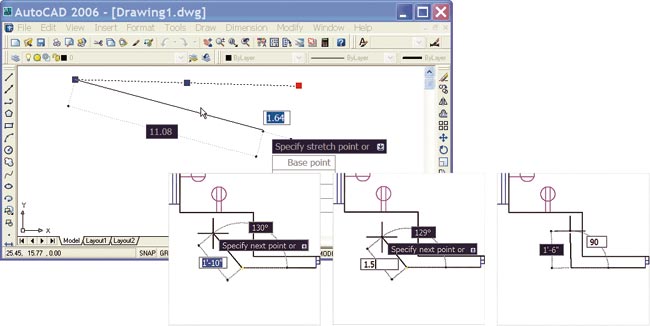
Anyone who ever thought that it would be difficult to add significant new functionality into a 20+ year old CAD product like AutoCAD will be very surprised at the many improvements and new features Autodesk has come up with. But perhaps the single most useful enhancement is something Autodesk is calling dynamic input.
As you draw, the command prompt appears adjacent to the cursor, and you can dynamically view dimension values, such as length and angle, and type values into dynamic input edit boxes. For example, to draw a line, you can select a starting point, drag the cursor a bit, type a distance value, press TAB to switch to the angle field, and then type the angle value, all without ever taking your eyes off the drawing. When commands offer multiple options, pressing the down-arrow key displays a drop-down list of those options right at the cursor location.
You can control how and when the dynamic input fields appear, such as switching between Cartesian or polar coordinate input and changing the size and transparency of the dynamic prompts. Pressing F12 (or clicking a new DYN button on AutoCAD’s status bar) toggles dynamic input on and off, but we think most users will quickly find this new way of working to be an incredible boon to productivity. So much so, that they may decide to turn off the command line entirely to regain additional drawing real estate.
A subtler but no less significant improvement involves the way AutoCAD lets you select objects. Any user who has worn out their ESC key because they often select the wrong object will be delighted with AutoCAD’s new rollover highlighting feature. When you move your cursor over an object, the object immediately highlights, making it easy to differentiate, for example, between individual lines and arcs and an entire polyline.
In addition, when using a selection window or crossing window to select objects, AutoCAD now adds a transparent box. The box background is coloured blue for a window selection and green for a crossing window. Again, users have complete control over the operation and appearance of this new feature.
Dynamic Blocks
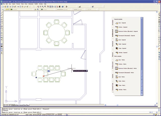
Most users have extensive libraries of blocks for all manner of standard components and symbols. The problem with blocks, however, has been that you need a different block for each instance of similar but slightly varying geometry, such as hex, cap, and machine screws. AutoCAD’s new dynamic blocks let you define a single block with multiple variations. Once defined, you can insert the block and then change its size and appearance dynamically within the drawing. The idea is to reduce the number of individual blocks within your block library.
Dynamic block definitions can contain multiple representations of a particular symbol, such as top, front, and side views, or multiple sizes. Upon insertion, you can choose which representation to use. Dynamic blocks can be defined with multiple insertion points that you can cycle through during insertion. Or you can create a block that automatically aligns itself with adjacent geometry when you insert it.
Dynamic blocks offer endless possibilities. Imagine inserting a conference table and being able to select the type of chairs arranged around its perimeter. Next, imagine grabbing the end of the table, stretching it, and having additional chairs automatically added.
You insert dynamic blocks the same way as you insert an old fashion block, and using dynamic blocks is pretty straightforward. But creating dynamic blocks is not a trivial task. To do so, you use a new Block Definition Editor and Block Authoring palette. After specifying the name for the new block, AutoCAD shifts into a new block definition mode. The existing drawing disappears and a new drawing area appears with a beige background. You then create the block geometry using standard AutoCAD commands, add parameters to the geometry (such as distance, rotation point, or visibility), and then add actions to specify how each property will change. You can also constrain properties. For example, if you’re defining a door, you can specify that the size of the door can vary in 1-inch increments, from a minimum value of 1′-6″ to a maximum value of 3′-0″.
When you create a dynamic block, you are basically programming the geometry to behave in an intelligent fashion – albeit using a graphical interface rather than code. Dynamic blocks offer lots of promise, but like the sheet sets introduced in AutoCAD 2005, it’s going to take users a while to master this new capability.
Annotation
Drawings consist of both geometry and annotations – text, dimensions, block attributes, and tables – to help convey information. AutoCAD 2006 provides a host of new features to make their creation and modification much easier.
In-place editing of text, long available for AutoCAD’s multi-line text, has now been extended to single-line text as well. Instead of displaying single-line text in a dialog box, the text remains on-screen as you edit it.
The multi-line text editor has also been enhanced to the point that it provides virtually the same functionality as any good word processor. You can now automatically create numbered or bulleted lists, and if you later add or remove items from the list, the items in the list renumber themselves automatically. You can also control the oblique angle of text, text tracking, and width factor directly within the multi-line text editor, rather than having to define these settings first in a text style.

In spite of AutoCAD’s existing wealth of dimensioning capabilities, Autodesk has still found ways to improve these tools in AutoCAD 2006. You can now assign the linetype, line weight, and colour of extension lines independent of other dimension settings and also create extension lines that have a fixed length, so that the extension lines don’t have to touch the geometry to which they are associated. Additional dimensioning capabilities include two new commands: DIMARC lets you dimension the length of an arc; DIMJOGGED lets you dimension radii of large curves when the dimension line cannot extend to the arc’s center point. A new Flip Arrow option lets you flip the direction of any dimension line arrow.
For years AutoCAD users have been creating tables for use as parts lists, bills of materials, schedules, and so on, often either laboriously creating them manually or extracting attribute data to an external file, such as an Excel spreadsheet, and then importing it back into AutoCAD as an OLE or table object. Those processes are no longer necessary. AutoCAD 2006 includes enhancements to the program’s Attribute Extraction wizard that let you extract attribute data directly to an AutoCAD table. You can easily preview, sort, and reorder data within the wizard. Once you’re satisfied, you can extract the data to an external file, a table, or both. Other enhancements let you perform calculations on table data directly within AutoCAD, reducing the need to rely on external spreadsheets.
Hatching and other improvements
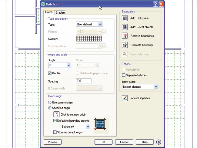
Filling a bounded area with a hatch pattern has long been an easy task in AutoCAD, but users still have numerous pet peeves. For example, the appearance of the hatch pattern depends on the boundary’s location in relation to the drawing’s origin. In AutoCAD 2006, you can specify the hatch origin while creating or editing the hatch by either picking the origin point or basing it on the extents of the bounded area. Other new hatching options let you apply the same hatch pattern to multiple areas at one time, but create them as separate hatch objects. AutoCAD can also now determine the area of a hatched space. When used in combination with AutoCAD’s data fields, users can easily create labels that display the hatch area. If you subsequently change the size of the hatch area (by stretching its boundary, for example), the area recalculates and the text updates to reflect the change. This capability has endless possible uses.
The list of improvements continues, and indeed some of the more subtle changes may have the greatest impact on user productivity. For example, the ROTATE and SCALE commands now include a copy option so that you can create new objects as you rotate or scale them. AutoCAD’s COPY, MOVE, and STRETCH command now individually retain their most recent displacement values. The OFFSET command lets you offset an object multiple times without having to reselect the object, and the command includes new options to erase the original object and to place the copies on either the same layer as the original or onto the current layer. And virtually all of AutoCAD’s editing commands now have their own undo function, so you can reverse just the most recent action, rather than the entire command sequence.
Even more subtle, users can now override common settings and command actions. For example, I often use the FILLET command to simply extend lines to their intersection point, but this requires first changing the current fillet radius to zero. Now, users can fillet or chamfer objects using a zero radius or chamfer distance by pressing the Shift key when selecting those objects to override the current radius or distance value. Similarly, you can hold down the Shift key to override AutoCAD’s Ortho mode (instead of pressing F8 to actually turn it off), press Shift+A to temporarily override current object snap settings, or press Shift+E or Shift+M to temporarily turn on an endpoint or midpoint object snap, respectively.
When you type commands, a new auto complete function lets you enter just the first few letters and then press the Tab key to cycle through matching command names. AutoCAD 2006 displays smooth transitions when zooming and panning, similar to the behaviour of Autodesk Inventor. Users can customize the scale list used in various dialog boxes to add custom values or eliminate scales that they don’t ever use. A new Drawing Recovery Manager makes it easy to locate and restore backup files or automatically saved versions of drawings without having to manually search through folders.
A new QuickCalc window lets users perform calculations in a more intuitive fashion than AutoCAD’s old command line methods. Toolbars and windows can now be locked. Multilines have been improved somewhat. A new JOIN command lets you combine individual segments of like objects into a single object. Most of AutoCAD’s UI customisation has been unified into a new XML-based Custom User Interface (which also means that users will no longer be able to modify menus by editing ASCII text files). The list really does go on and on.
I’m pretty jaded when it comes to AutoCAD. It was my first CAD program. I’ve been using it since 1984, have written over a dozen books about it, and spent a decade developing and selling AutoCAD add-ons. I figured AutoCAD had just about gone as far as it could go. Happily, Autodesk has proven me wrong. I suspect users are going to be quite pleased as well.